Background/Motivation
I’ve always been fascinated with mechanical clocks, and the escapement in particular is kind of addictive to watch. One tooth of the escape wheel just gets let go by the anchor, and the other side is just in time to catch the next one. You always wonder, will it miss or not? Right? It’s kind of hypnotizing to watch how it works. So I always wanted to make one for myself to look at, basically.
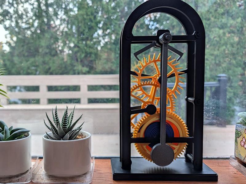
And I wanted it printed completely: no screws, no bearings, no metal and no glue. So this is my take on it, a Graham dead-beat escapement, the kind used in good regulator clocks, driven by a printed PETG mainspring.
This post is the story of how it went from “it doesn’t turn” to “it ticks”. For the files and the step-by-step assembly, see the MakerWorld page.
Model Design/Modeling
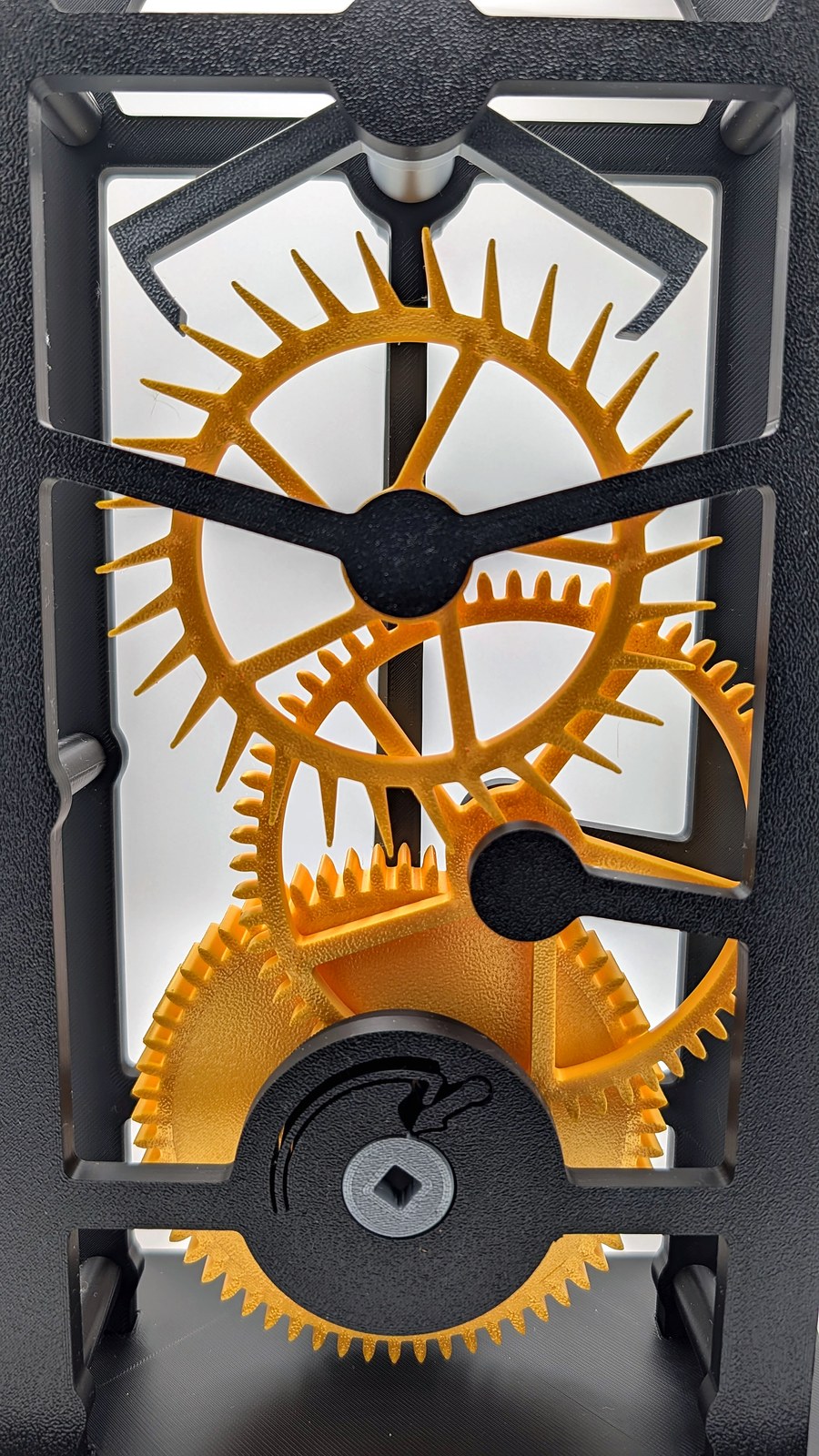
The look is a skeleton clock: a black portal frame on a base, so you can see the whole train, with the gold wheels as the focus and the pendulum hanging in front.
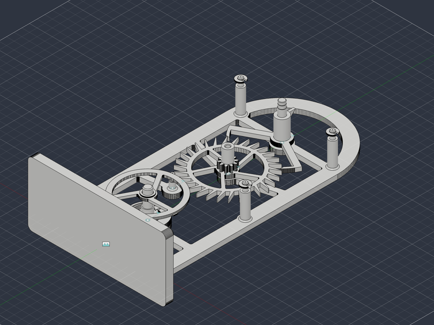
On paper everything worked. The first full build told a different story.
The first dry assembly: five problems at once
When I put the first full set together, I found five things wrong:
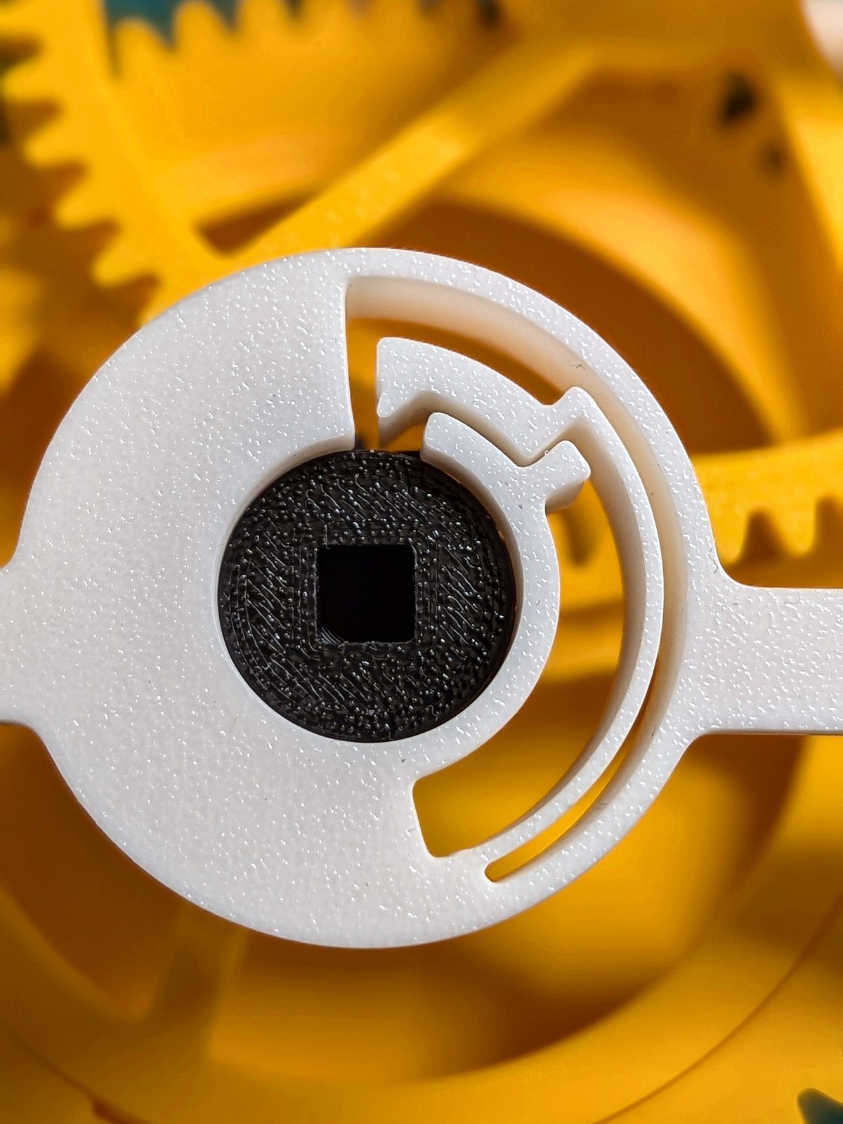
- the click (the ratchet that holds the spring) didn’t hold, the pawl just slipped out
- the wheels were stiff
- the barrel lid was loose and rattled
- the pendulum bob touched the front plate when the clock tipped back a bit
- one frame leg lifted during the print, the first layer didn’t stick well
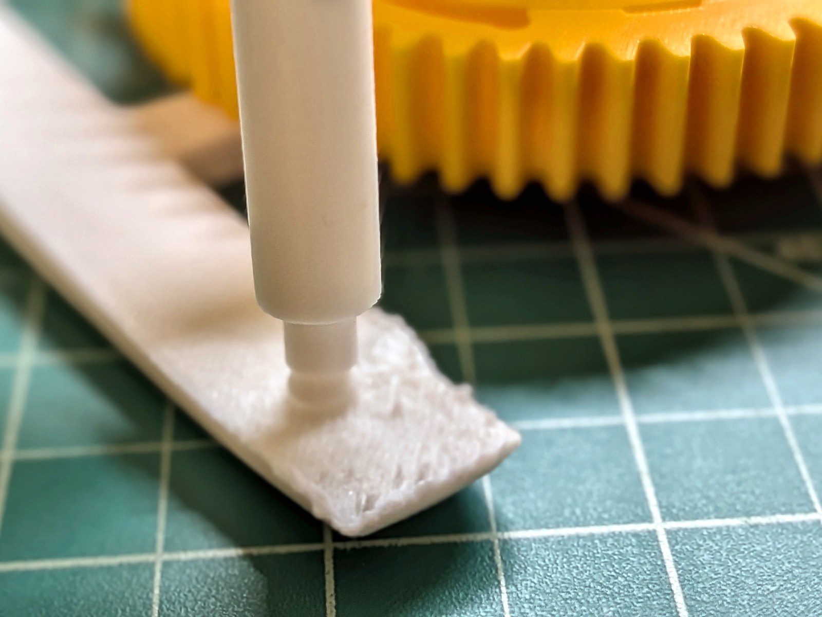
Some were easy. The bob got a window in the front plate behind it, and the frame got a brim. The other ones took a few rounds.
Stiff wheels: the test coupon lied
The wheels were stiff even with the front plate off, so it was the back pin and the bore itself, not the plate alignment. The funny part is that I tested this fit before with a small coupon, and it was fine.
The problem is that the coupon was a thin ring, and the real wheel hub runs much longer over the pin, inside 6 walls. So I printed a new coupon with exact copies of the real hub at three bore sizes. The smallest one was as stiff as the real wheel, and the two bigger ones turned freely. Lesson learned: a fit coupon has to copy the real part, same length and same walls, otherwise it doesn’t tell you much.
It needed a full wind to start, then stopped
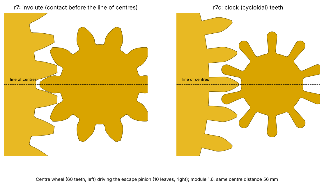
Even with free wheels, the train needed a full wind to get going and then stopped. After some reading, the reason was the gear teeth. Normal (involute) gear teeth start pushing before the line between the two centres, and in that part of the mesh the teeth rub a lot. In a car gearbox that doesn’t matter, but a clock train runs on very little force.
Real clocks use a different tooth shape (cycloidal), where the contact happens after the line of centres. So I changed all the teeth.
The pawl that kept sliding out
The click pawl is printed in place and held in its socket by a small bead. It kept sliding out, and it took a while to see why: a groove I cut later in the model removed most of that bead.
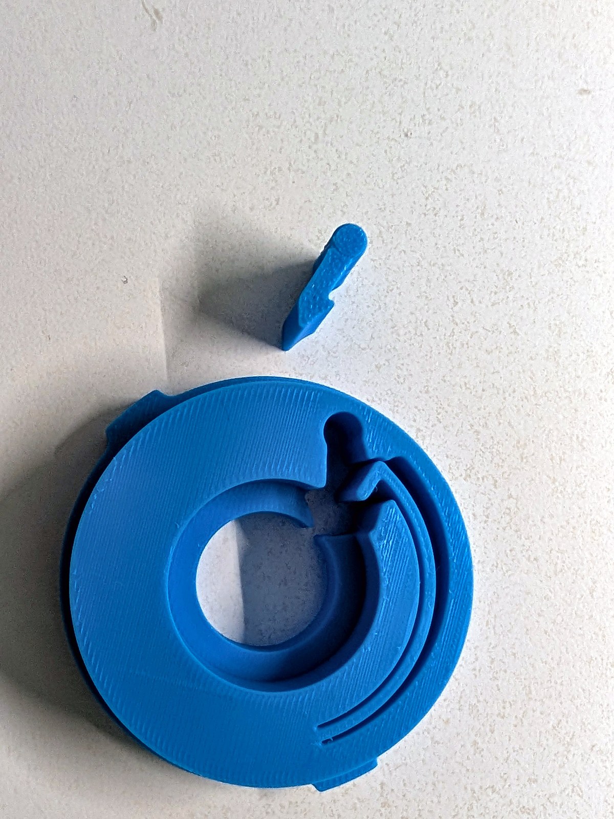
So the order matters. The bead has to be added after the cut, not before. After that fix, the pawl stays put and the click holds the spring.
If you ask me which part of the clock I like the most, after the escapement of course, it’s this one: the pawl and the ratchet. I really like that the pawl is printed in place, and then when you wind it, you hear the click. It’s so satisfying, and it’s just so smooth. There’s nothing else to put it together, no pin, no threading, just the pawl printed in place, and it works perfectly. I hope you guys enjoy the clicking sound of the ratchet as well.
Setting the beat
The pendulum first sat on a friction clamp so you could turn it to set the beat (an even tick-tock). It turned way too easily. The clamp turns along the layer lines, and with a 20 cm pendulum, a light touch is a lot of force. In the end I made it a threaded boss with a thumb nut, plus a small printed spanner to hold it while you tighten. Loosen, set the beat, tighten.
Printing Notes
A few things in the slicer made a real difference on this one:
-
Slits inside the gear teeth. With the default
Arachnewall generator and 6 walls, I saw thin slits between the wall loops along the middle of the teeth. A fewArachnesettings changed (minimum bead width, minimum feature size, transition settings) and the slits are gone, for about 6 extra minutes of print time. Everything is set in the 3mf.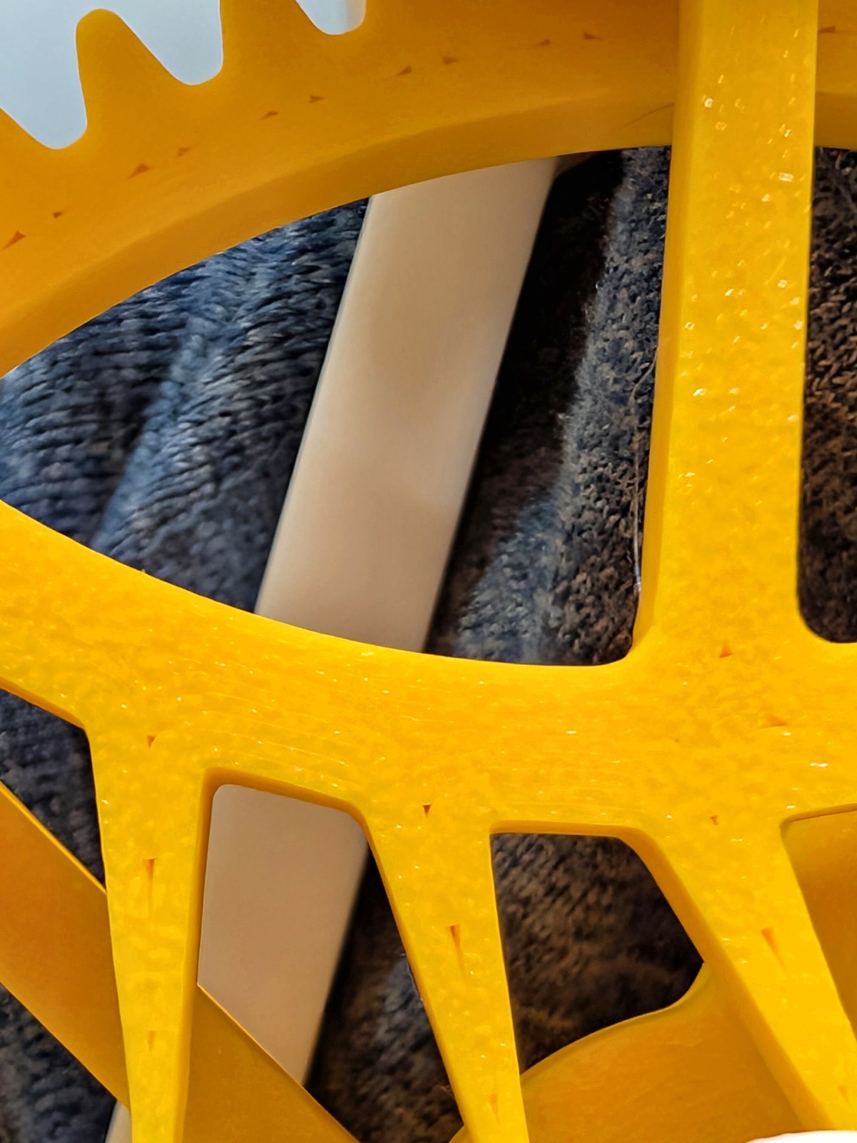
-
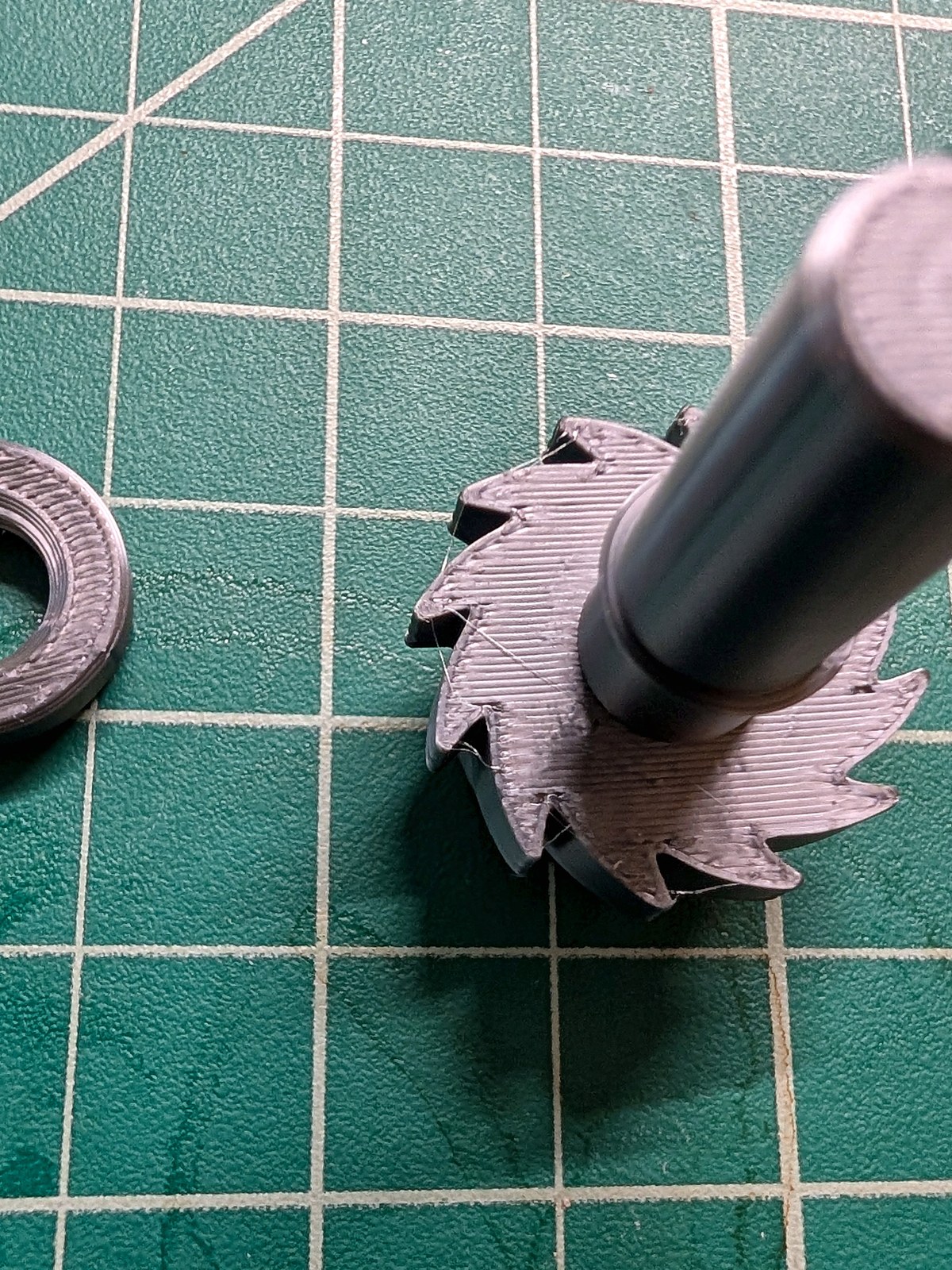
Stringing. There were some mild strings across the pendulum hole and between the ratchet teeth. Turning on
Avoid crossing wallsfixed it. It’s on in every plate now.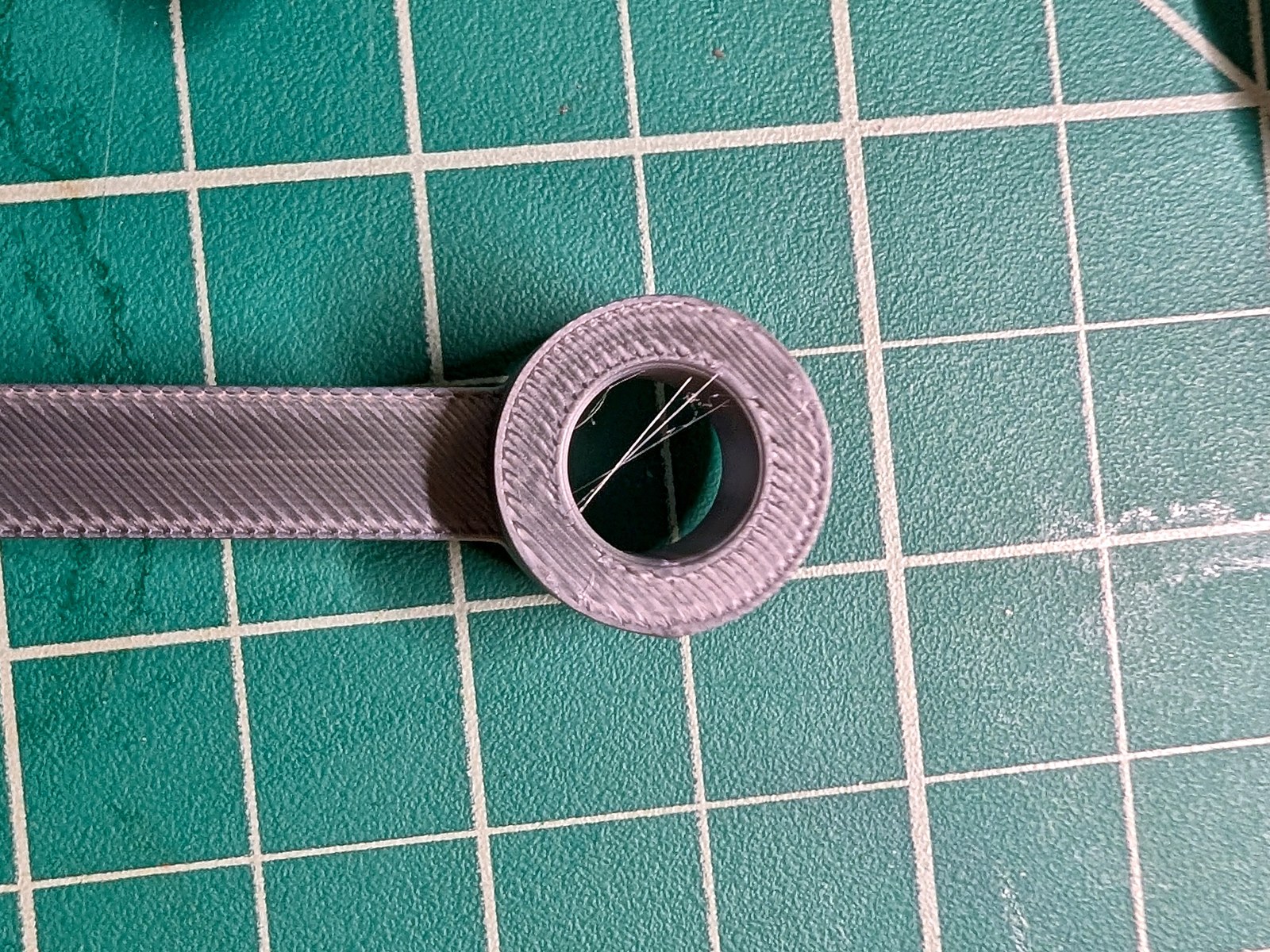
-
Colours. I printed the frame in PLA Basic Black, the wheels and barrel in PLA Silk+ Gold, the anchor and pendulum in PLA Silk+ Titan Gray, and the spring in PETG. The silk wheels worked fine with the fits, which I wasn’t sure about at first.
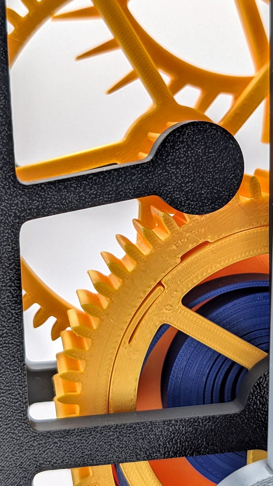
The two frame plates are about 31 cm long, so it needs an H2-size bed for now.
Model Usage/Resources
Wind it with the key from the back, set the beat, and watch it tick. On my build it runs about 20 minutes on a full wind, and honestly, I can stare at the escape wheel for those whole 20 minutes. It’s a movement to watch, not a timekeeper, there are no hands. It also gets smoother after the first few windings, and a little grease on the pins and pallets really helps.
All the files, the 3mf with every setting and the step-by-step assembly guide are on MakerWorld.
If you’d like a version that fits a 256 mm bed, leave a comment there or below. If enough people ask, I’ll split the frame.
I hope everyone enjoys it as much as I do.